Reverse Engineering Spur Gears
GearGen.XYZ was built around the idea of creating gears from scratch using fixed parameters like center distance, specific gear hob cutting tools, and existing gear geometry. Creating a gear that can be cut by a specific gear hob makes reverse engineering an easier process. This guide is meant to help you do that by walking you through the process of reverse engineering a spur gear.
Before we begin, it is important to understand the configuration sidebar and the specific input cards and the parameters within that are required.
1. Configuration Sidebar Required Fields
Take note of the input parameters below. You will notice that there is no field for entering a diameter. Only two parameters are required: number of teeth and the span measurements.
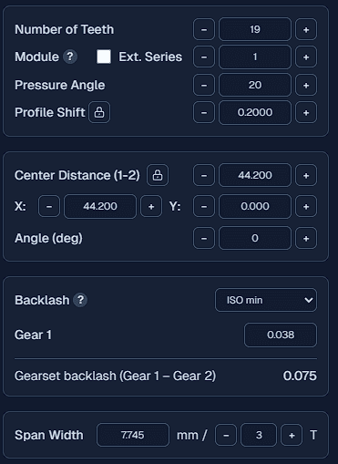
1. Main Parameters
The only manual entry needed in this card is the number of teeth. The remaining parameters are entered after finding the base pitch using the Base Pitch Table Lookup tool.
2. Span Measurement
This card is essential for determining both the base pitch and profile shift. To find the base pitch, you must take two separate span measurements.
2. The Importance of Base pitch
Most gear reverse engineering tutorials suggest starting with measuring the outer diameter and then dividing it by the number of teeth plus 2 to get the module. While this is helpful to get a starting point, it fails to provide the correct module when a profile has been applied to the gear. Furthermore, no diameter measurement can accurately determine the pressure angle.
The diameters should still be measured, but primarily used to verify machining parameters: use the outer diameter for the turned blank size and the root diameter to check which tool was used (e.g. 2.25, 2.35, or 2.4 whole depth hob).
To accurately find the module, pressure angle, and profile shift you must first find the base pitch.
Finding the base pitch via Table Lookup
The base pitch is the arc length on the base diameter of the gear, representing the distance from the start of one involute to the start of the next.
You can calculate it by taking two span measurements with a 1T difference apart. For example a span 4T minus a span of 3T. This value is then compared against a lookup table to find the base pitch. I have created a calculator to make this process easier. Base Pitch Table Lookup
Below is an example of how to enter the span measurements into the Base Pitch Table Lookup tool. It shows the closest match from the lookup table. Take multiple measurements and compare the results to find the most accurate base pitch.
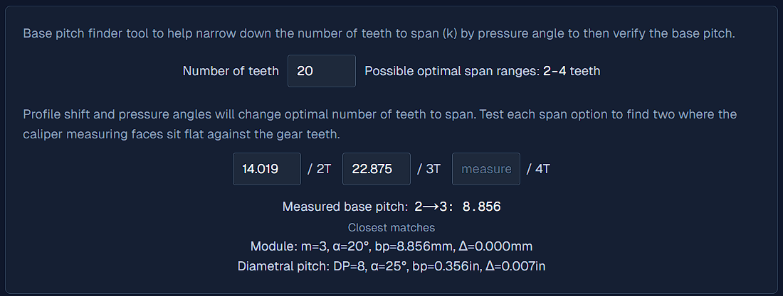
Note: It should be almost an exact match, expected error is ~0.025mm (~0.001") or less for the base pitch.
3. Determining the Profile Shift
Once the base pitch is established, use a single span measurement to find the profile shift.
- Enter the main parameters (Step 1).
- Enter the span measurement and the number of teeth.
- The profile shift will automatically be calculated and displayed in the profile shift field.
4. Verifying Gear Parameters
While this method is quick and effective for both spur and helical gears, it is not foolproof. Certain micro-geometry modifications can cause measurement errors:
Tip Relief: This common modification thins the tips of the gear teeth (typically by 12 to 50 μm). If your span measurement includes the tips, it may be slightly inaccurate.
Crowning: This removes a small amount of material from both ends of the lead, which can also affect calipers or micrometers.
Pro Tip: To check your work, roll a physical gear cutting tool against the gear. If it does not roll smoothly, re-evaluate your measurements. For absolute certainty in high-precision applications, a Gear Measuring Machine (GMM) is required to verify all parameters.